Automatic fire sprinkler systems are installed for two main reasons; property protection or life safety. In both cases their efficiency in controlling and extinguishing fires has protected lives and the environment for over one hundred and twenty years.
In both of these cases an essential part of the system is the water supply. This can take the form of a direct supply from the local water service main with or without a booster pump or, more reliably, having water stored in a tank with a pump or pumps to deliver the water to the sprinkler system.
The most common arrangement is a single water storage tank with two fire pumps, each capable of meeting the needs of the sprinkler system.
For enhanced reliability, the water storage tank can be split into two half-capacity tanks. This ensures that there is always a water supply available to the sprinkler system, even when one tank (or any of its equipment) is being serviced or maintained.
In both cases their efficiency in controlling and extinguishing fires has for over one hundred and twenty years protected lives and the environment and it should be accepted that all sprinkler systems will protect lives by restricting fire spread and protection escape routes.
Property protection systems are often installed at the request of the building occupier’s insurer to protect the business by ensuring the building and contents are protected against fire.
Some systems are installed to comply with building or fire regulations primarily to protect employees, the public and fire fighters from the risks of fire. This type of system should be more accurately referred to as ‘enhanced availability’ sprinkler systems but are more commonly called ‘life safety’ sprinkler systems and include a range of added features which reduce the possibility that the system will ever be non-operational due to scheduled service and maintenance being carried out.
Balmoral Tanks gratefully acknowledges BAFSA for its kind assistance with the text used on this page
Contact us now for expert technical advice on fire fighting sprinkler tanks
Fire protection technical guide
Standard of construction for fire fighting tanks
Globally, there are two main standards covering the design, manufacture and installation of fire sprinkler tanks: Loss Prevention Council Board (LPCB) and Factory Mutual (FM).
It is essential that the water storage tank is of robust construction and designed and constructed with minimal requirement for maintenance or servicing. Balmoral firefighting water storage tanks carry FM approval and the company is going through the process of adding LPCB approval to its portfolio.
Sprinkler tanks are also listed by the US insurers’ certification body, UL, for use on specified sites. For contracts designed to NFPA 13 (US National Fire Protection Association Codes) either an FM or LPCB listed tank can be used subject to insurers’ approval.
The above standards extend to cover all aspects of fire safety including sprinkler heads, pumps, booster sets, ladders, immersion heaters, vortex inhibitors and maintenance of the system.
Full technical details covering both LPCB and FM standards can be found on their respective websites.
BS EN 12845:2015+A1:2019 is a CEN standard covering all aspects of a fire sprinkler system and is available on the BSI website. This is a technical document that references specific aspects of firefighting storage tanks used in the LPCB and or FM standards.
Gravity
Water quality
How much water is needed?
Full holding or reduced capacity
What duration of water should be provided?
Tank support base
Tank painting
Tank location
Planning approval
During the planning stage drawings and details of the location of external sprinkler tanks should be submitted to the insurer for their approval and comment before installation take place.
FM Approvals
Tank shell
Tank roof
Accessories
Corrosion protection
Tank heating and insulation
References
Balmoral FireFlow™ vortex inhibitor
Fire fighting water tanks require a large, fast flowing volume of water with a vortex inhibitor playing a key role in preventing air being drawn into the system and reducing the flow. Vortex inhibitors are fitted to the outlet pipe of the pumped water system.
Standards require the usable water level to be no less than 100mm above the lowest suction point, the height of the vortex inhibitor also affects the effective capacity within a sprinkler tank.
Simple vortex inhibitors are available commercially; however the Balmoral FireFlow vortex inhibitor provides a significantly improved design which optimises both the capacity of the tank and the flow rate.
Balmoral’s vortex inhibitor was designed using computation fluid dynamics to remove turbulent areas that would otherwise reduce the flow rate.
Balmoral’s unique design fully meets the requirements of BS EN 12845 standards, including pipe dimensions, flow rate and mechanical strength, but with the advantage of increasing the effective capacity of the tank and decreasing the suction loss through the vortex inhibitor by an industry-leading 30%.
The injection moulded vortex inhibitors are made from structural thermosetting polyurethane, are fully corrosion resistant and range from 80-450mm in diameter. These PU materials are used by Balmoral’s offshore division at water depths of 2000m and beyond.

Accessories and ancillaries
Fire fighting sprinkler tanks
For optimum functionality the following accessories will usually be installed on a Balmoral fire fighting sprinkler tank:
- A reliable water supply connection (usually direct from the service main) capable of refilling a full holding capacity tank in 36 hours or with sufficient flow to replenish a reduced capacity tank in 30, 60 or 90 minutes as necessary
- Flow testing facility to prove the flow rate of the infill. Adequate drainage should be provided for disposal of water during testing
- Float or Ball valve/s on the tank infill pipe. These must be located in a secure housing on the tank roof
- A duel element electric immersion heater to prevent ice forming on the water surface in the area of the ball/float valves on external tanks
- Electric float switches to transmit signals to the BMS or fire control panels to indicate the high/low level volume of water in the tank
- A drain valve at low level
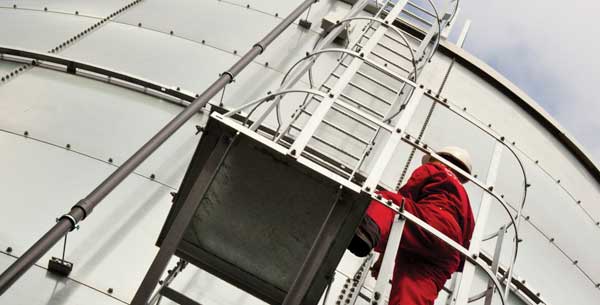
- A gated ladder to allow personnel to get to the inspection and maintenance platform on the tank roof
- Third party pump suction pipe with an electrically monitored gate valve, locked open
- A rigid roof that excludes daylight, can withstand snow loads and prevents any matter falling into and contaminating the water
- Most tanks have a vortex inhibitor fitted at the inlet of the pump suction pipe to prevent air getting drawn into the pump. For NFPA and FM Global contracts the vortex inhibitor must be constructed as detailed in their data sheets
- Trace heating and lagging to all exposed water filled pipes, by others
- A 25mm warning pipe is installed just above the high water level to give an early warning of ball valve malfunction
- An AB airgap arrangement with side spill over weir assembly and cowl
- A larger bore overflow pipe
- An access hatch is provided at ground level to allow access during tank construction and evacuate personnel in an emergency
- A contents gauge or device which shows the level of water in the tank
- Some sprinkler tanks will have a fire brigade inlet installed. This allows the brigade to ‘top up’ the sprinkler water storage if necessary
- A sump can be formed in the concrete tank base. This allows the sprinkler pump to draw water to a lower level from the tank.
Pipework configuration
The inlet or delivery pipe can enter the tank through either the side wall at the top of the tank or into a raised chamber. Flow can be controlled through a ball valve, equilibrium float valve or automatic float switch.
Overflows should be positioned in accordance with the required air gap, and all outlets (suction), drains and overflows will come through the side walls of the tanks.
Overflows and warning pipes terminate at high level, horizontally, and can be extended to the floor if required.
Pipe connections
Customers are asked to provide full details when ordering. The type of pipe connection should be specified together with the relevant standard to which the coupling flanges are drilled or the pipes screwed. To assist delivery, the size and position of each connection should also be specified at the time of ordering. Ball and gate valves and all pipework, including bends and flanges, can be supplied if specified at the time of ordering.
Connections can be supplied as flanged stools to BS4504, ASA or DIN standards, or, for small pipework, screwed sockets to BS1387. The connections are fitted to the plates in positions agreed at the time of order.
Low level access panels
The low level access panel was introduced by Balmoral Tanks to address confined space issues. Essentially, when a tank is being constructed onsite, it will ultimately become a confined space as the installation team completes the build.
Ball Float Valve
These are installed at the end of the incoming water supply pipe and automatically keep the tank full.
Fire tank solutions and information
Contact us to find out how we can help you solve your current technical challenge
Balmoral Tanks Ltd
Contact us | Locations
Reg No. SC300656